A site plan is a drawing of what is existing and what is proposed on a lot. The minimum sheet size is 18 inches x 24 inches. You must verify and accurately depict all locations and dimensions of property lines, setback distances, streets, rights of way, and easements. Where a project also submits civil plans, the residential site plan and civil plans must be coordinated as to not include contradictory information. For preparation information see Electronic Plan Requirements and Electronic Review Efficiency.
Note: Aerial photographs are not acceptable site plans.
What must a site plan show?
A site plan must include the legal description and site address; North arrow; graphic scale (1" = 10' or 20'); the name, address, and phone number of the preparer; and the following information:
- Property lines with dimensions.
- Streets or alleys abutting the property; identify the street name.
- Contour lines for both existing and proposed grades at 2-foot intervals. NAVD 88 is the required vertical database. Use the same datum in all of the elevation information.
- Setbacks—including front-, side-, and rear- yard dimensions—must be labeled. Also show any plat-required building setback lines and setback lines from Protected Areas, if applicable.
- Easements on or adjacent to the property, including non-motorized open space, utility drainage, native growth protection, and access easements. Include the King County recording number for existing easements.
- Utilities: Include the location of all existing and proposed utilities below and above the ground. Include street lights and fire hydrants. Show proposed water, sewer, and storm drainage systems.
- Structures: Show the location, size and use. Show distances to property lines.
- Accessory Dwelling Units (ADUs): Number of accessory dwelling unit(s) proposed and total number of ADUs on site. The square footage of the ADU(s) along with the required parking stalls.
- Cottage Housing development: Cottage housing proposals need to provide lot coverage and impervious surface calculations related to covered porches. A total open space calculation along with a common open space need to be provided.
- Courtyard Housing development: Courtyard Housing development proposals shall provide an impervious surface calculation for the total open space.
- Trees: Depict all trees on the site plan. Label the tree species (Latin name) and their diameter at breast height (DBH), as well as depict required Tree Protection Zones. Indicate which trees are proposed for removal. Provide a tree credit calculation per LUC 20.20.90.
- Rockeries and retaining walls: Show top and bottom elevations at 10-foot intervals or where a 2-foot change in height occurs and, if applicable, where it crosses the setback line.
- Critical areas such as streams, wetlands, areas of special flood hazard, steep slopes greater than 40 percent, unstable soils, coal mine hazard areas and the buffers and structure setbacks that protect critical areas.
- Floor area ratio calculations: Include the gross square footage of the structures on the lot in relation to lot area.
- Lot coverage calculations to show the area of all structures in relation to lot area. Lot coverage is based on the lot area with the square footage of any critical areas and stream buffers subtracted. Habitat for species of local importance and coal mine hazard areas are not subtracted.
- Impervious surface and hardscape calculations show the square footage of all impervious surfaces and/or hard surface coverage on-site in relation to the lot area.
- Plat conditions such as building setback lines (BSBL) should not be confused with zoning setback lines and minimum floor elevations. Note: Refer back to “Easements” and “Critical Areas” for additional information.
- Building height calculations: Calculate height from elevations taken at evenly spaced intervals not to exceed 10' around the perimeter of the structure. Show the table calculations on the site plan. On the elevations sheets, show the existing and finished grades and the height calculation to indicate compliance with the height limit.
- FEMA floodplain elevation must be shown for sites on a shoreline and any streams with a floodplain mapped by FEMA.
- Other Information: A geotechnical report may be required as a condition of plat approval, for specific site improvements (i.e., rockeries and retaining walls), or as soil conditions dictate. The city may require additional information as needed.
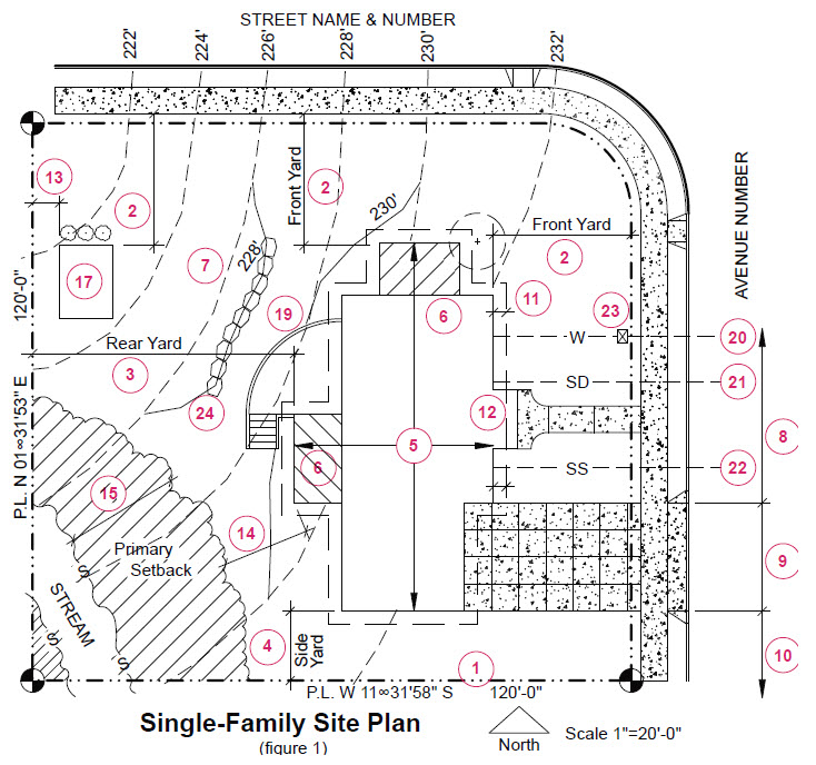
Numeric Legend for Key notes above
- Property line
- Front-yard setback dimension (applies to all structures)
- Rear-yard setback dimension (for primary structure)
- Side-yard setback dimension
- Existing building footprint
- Proposed additions or new structures
- Existing and proposed contours (2 ft. interval)
- Distance from driveway to face of curb/ edge of paving
- Driveway width
- Distance from driveway to neighbors’ driveway
- Depth of eve
- Setback intrusion by minor structural element (porch)
- Rear-yard setback dimension for accessory structure
- Building setback dimension from buffer
- Critical area elements
- Garden shed at 10 feet above finished grade
- Minor structural element (existing porch)
- Proposed additions to primary structure
- Deck at 30 inches above finished grade
- Water line location and diameter
- Storm drain diameter and location
- Sanitary sewer diameter and location
- Water meter size and location
- Rockery location and height
Note: The following additional items are excluded from the above site plan, but they are required when warranted by existing site conditions. See the land use planner.
- Ordinary High Water Mark (O.H.W.M.)
- Setback from O.H.W.M.
- Floodplain elevation
Definition of Site Plan
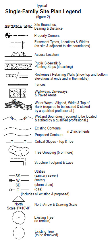
A site plan is a to-scale drawing of existing and proposed site development. The required elements and information, along with a graphic representation of each, are portrayed on the drawing on the opposite page. No other building information, such as energy calculations, should be on the site plan.
Site Topography
The existing and proposed topography is required to be shown on the site plan at a minimum of 2-foot intervals. The topography was excluded from the sample site plan in order to make it easier to read.
Lot Coverage
The calculation of lot coverage is required to be shown on the site plan. Lot coverage is the total building footprint area as a percentage of the total lot area. However, the total lot area excludes all critical areas and their related primary setback areas. The “footprints” included in this calculation must include all primary structures, all accessory structures, and decks that exceed 30 inches above finished grade.
Additional information
This information is intended to provide guidance in applying certain Land Use Code regulations and is for informational use only. It cannot be used as a substitute for the Land Use Code or for other city codes, such as the Construction Codes.

